Last week, I discussed the anatomy of an automotive short circuit and described in detail why, if a wire is shorted to ground, the low resistance in standard wiring causes a gargantuan amount of current to flow, which in turn generates so much heat that it often results in melted wiring. In addition to the comments here on BimmerLife, I received several emails thanking me for explaining it.
Really, a short circuit is one of five distinct ways that an automotive circuit can fail. So, this week, I thought I’d finish framing this electrical house and give more context to “the short circuit” by explaining the other four circuit failure modes.
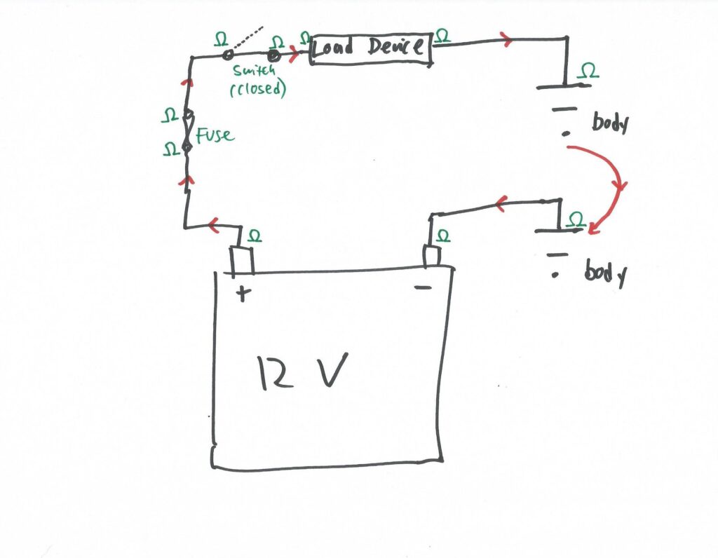
As I explained last week, an electrical circuit needs three things—a voltage source, a path for current to flow, and a load device. In a car, the voltage source is the battery (and, once the engine is running, the alternator). The load device is the thing in the circuit—the light bulb, the electric motor, etc—that’s performing the electrical work and using the flowing current in a constructive manner. The current path is the long wire from the positive battery terminal to the device, the short wire from the device to chassis ground, the chassis itself, and the ground strap from the chassis to the negative battery terminal. In addition, most real automotive circuits also have a fuse and a switch. Thus, as I showed last week, most circuits look like this:
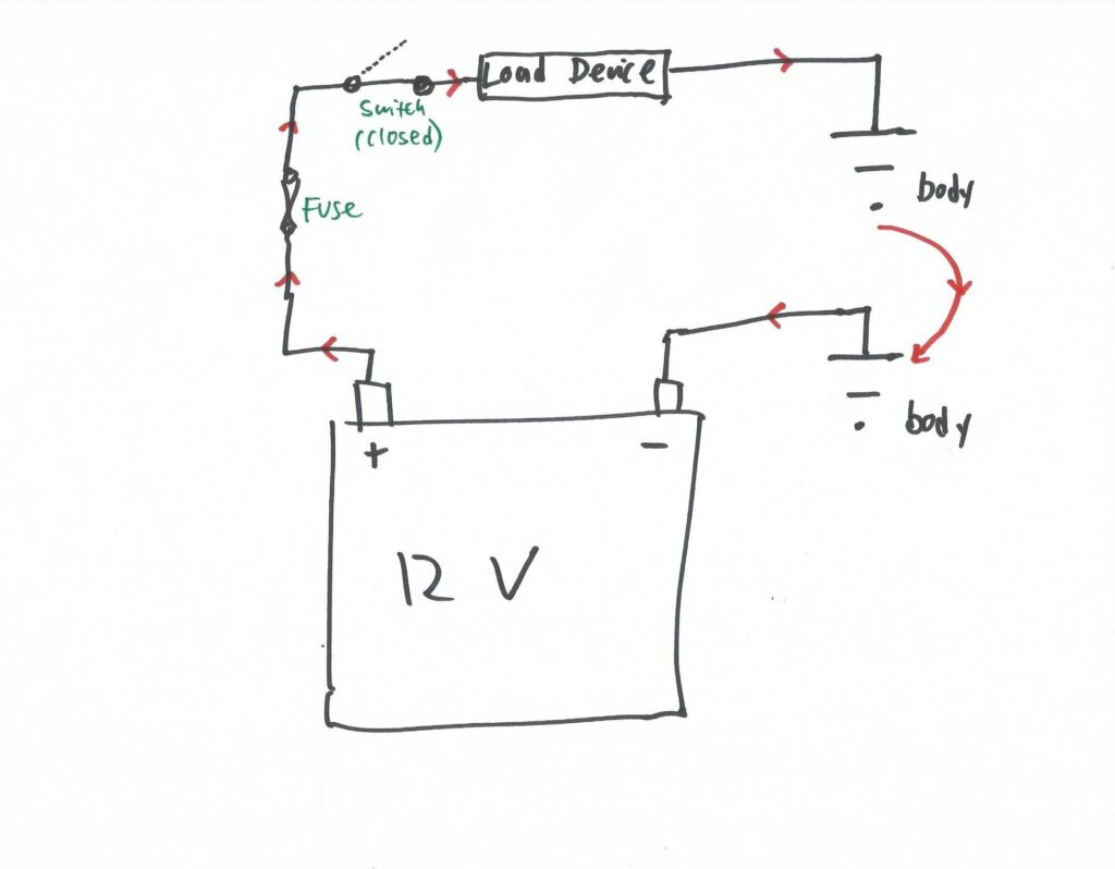
Basic but realistic electric automotive circuit with fuse and switch.
So now let’s talk about the ways a circuit like this can fail.
Failure #1: Open Circuit
For a circuit in a car to function, current needs to flow from battery positive, to the load device, to chassis ground, and from there to battery negative. If the circuit is “open” (if there’s a break in it anywhere), there’s no closed path to allow current to flow. Below, I show the same circuit above but with the switch in the open position. This intentionally creates an open circuit, so it’s perhaps semantics to call it a failure. However, the fuse being blown creates the same open circuit, but does so unintentionally, so that’s a failure, as is a broken wire and a bad ground connection.
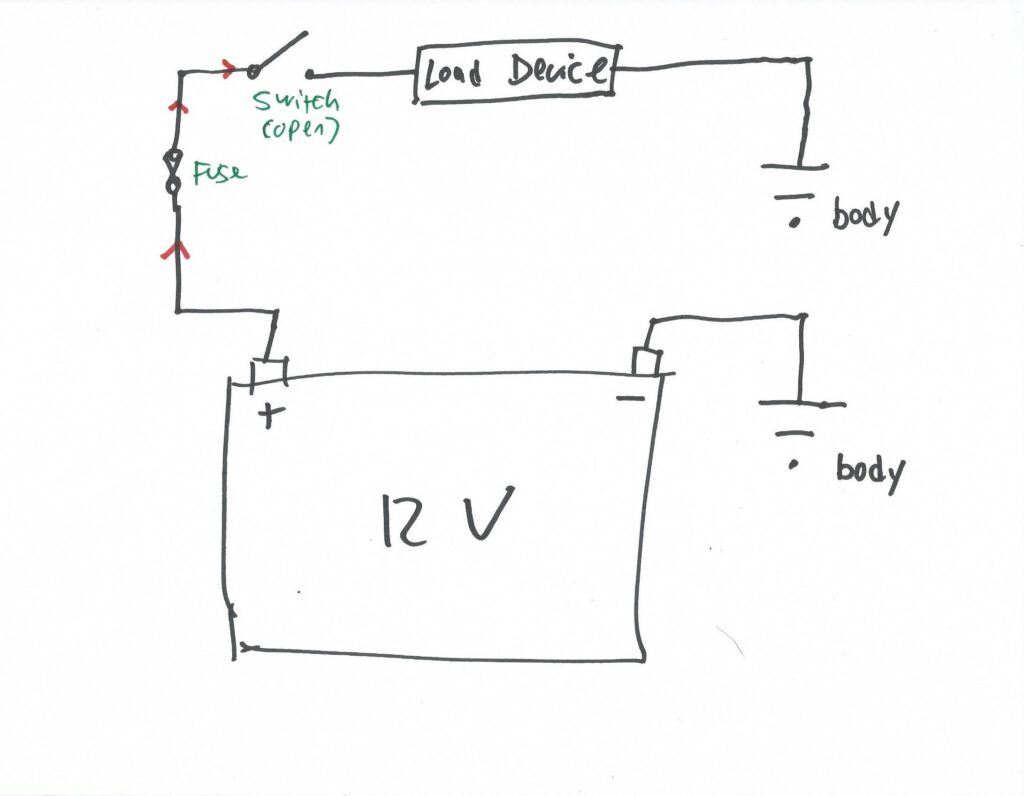
Opening the switch stops current flow and makes this an open circuit.
Looking at the above drawing, in the real version of the automotive circuit this represents, there’s a connection at every location where one of those black wire lines intersects one of those components. It could be a spade connector pushed onto a terminal, or a ring connector with a screw through it, or—gack!—a wire nut twisted over a pair of wires, or—barf!—something held on with electrical tape. The point is that wherever there’s a connection, there’s the possibility of it becoming detached and creating an open circuit. Yes, wires can break in the middle, but the odds of a connector pulling off, or a wire pulling out of the back of a connector, or a bad splice separating, are far greater.
Failure 2: Component Failure
Component failure can take several forms. In its simplest, it’s a special case of an open circuit. The figure below shows a light bulb with a broken filament. This is fundamentally no different than any other broken wire or pulled-off connector creating an open circuit that prevents current from flowing.
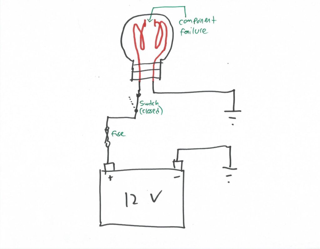
A burned-out bulb filament is an example of component failure creating an open circuit.
The other form of component failure is where the circuit is closed—current is still flowing through the component—but the component still isn’t working. This is the case with a seized electric motor. The flowing current may eventually cause the fuse to blow, at which point the circuit becomes open.
Some electrical tutorials don’t regard component failure as a type of circuit failure at all, as the failure is isolated to the component, not to the circuit wiring. I think that’s being overly pedantic. When things aren’t working and you’re troubleshooting, it’s crucially important to understand that the circuit contains power, wiring, and a load device. The device is part of the circuit.
Failure #3: Short to Ground
The third failure mode is the one I discussed in detail last week—a short to ground. The green path in the drawing below shows a short to ground after the fuse, so the fuse will save you—that is, it’ll blow before things melt (meaning it’ll melt in a controlled fashion before other things melt in an uncontrolled fashion). The red path shows a short before the fuse. With no fuse to blow, the battery will pump out whatever amount of current Ohm’s Law demands and the battery’s capacity will allow, generally resulting in melted wiring.
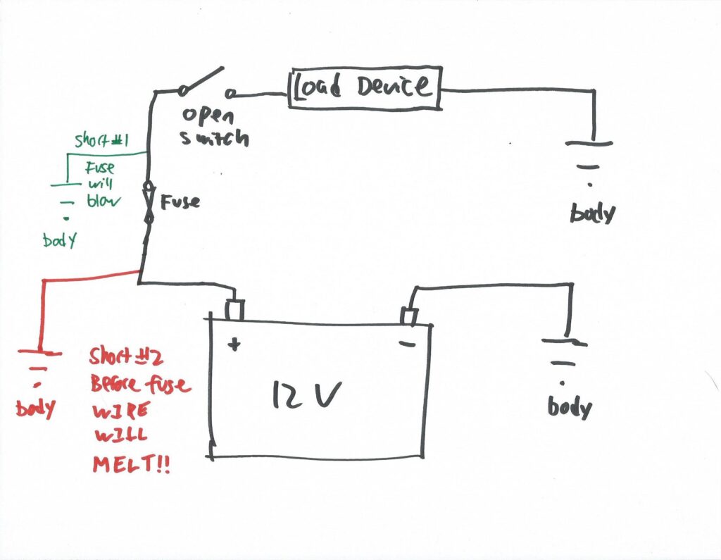
Two versions of the notorious short to ground.
Failure #4: Short to Power
Not as well-known or as well-understood as a short to ground is a short to power. This failure is less intuitive than a short to ground. Even using the word “short” is a bit misleading, as the current path isn’t necessarily any shorter—it’s just not the path that’s intended. A short to power is also not nearly as dangerous as a short to ground.
A sort to power is depicted in the figure below, where two light bulbs are independently connected to a battery. Each has its own wiring, fuse, switch, and ground connection. As pictured, the switch to bulb 1 is closed, so bulb 1 illuminates. The switch to bulb 2 is open, so bulb 2 should be out. But if there’s a short between the wire feeding power to bulb 1 and the one feeding bulb 2, then bulb 2 will illuminate even if its switch is open.
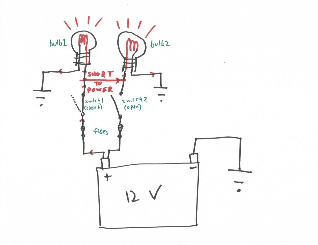
An example of a short to power.
This seems contrived? You don’t see how this could really happen? Okay. Close your eyes and imagine a 50-year-old wiring harness. Maybe it’s already had a short to ground pass through it, so wires have had the insulation burned off. Or maybe it’s just an old fraying cloth-wrapped harness with wires that have rubbed and chafed against each other since Gilligan and his pals were trapped on that island. Maybe the chafing is at a pinch point where all the wires pass through a bulkhead together or are held with a zip tie or a clip. Can you picture it now? Next time you hit the brakes and the wipers come on, I guarantee you you’ll say to yourself, “Oh! I know! It’s a short to power!”
Failure #5: High Resistance Failure
Last week, when discussing unintended resistance in a circuit, I broke it into two types—unintended low resistance and unintended high resistance. I said that unintended low resistance (what’s in a short to ground) is really bad and really dangerous, as it’s the kind of circuit failure that causes enormous amount of current to flow and results in electrical fires. Unintended high resistance isn’t nearly as dangerous, as high resistance does the opposite—it reduces the amount of current that flows. To be clear, unintended high resistance can generate heat, but it’s typically orders of magnitude less heat than a short to ground. It certainly can, though, cause a circuit to malfunction, as it prevents the needed amount of current from flowing through the load device.
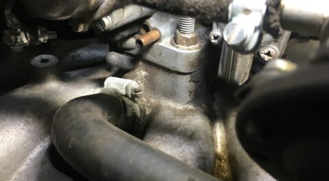
Unintended high resistance is usually caused by corrosion in electrical connections or rust on the mating surface of a ground connection. It can also be caused by an old terminal that’s become so loose on its post that there’s very little metal making electrical contact. Or by a crimp-on connector that isn’t crimped sufficiently tightly around its wire. Or by a multi-stranded wire where every strand except one has broken. In all of these cases, the connection can’t carry all the current that the circuit demands. The circuit may work intermittently, or may only work when engine rpms are higher which makes the alternator output higher voltage, or may not work at all. For example, problems with power windows that work intermittently or slowly when the motor itself appears to be fine are often due to corrosion at or inside the switches.
Unintended high resistance can be present everywhere the little Omega (Ω) sign is.
To find unintended resistance, there’s a technique called a voltage drop measurement where you set a multimeter to measure voltage and put the two probes on either side of a circuit connection. Note that this is distinct from a standard voltage measurement where the red probe is put on the positive leg of the circuit and the black probe is on the negative leg. In the voltage drop measurement, both probes are on the same leg of the circuit, and in close proximity to each other. For a low-current circuit like a light or small electric motor, you should see virtually no voltage drop across a connector, and maybe a few tenths of a volt at most across a switch. If you’re seeing more than that, the odds are strong that there’s corrosion.
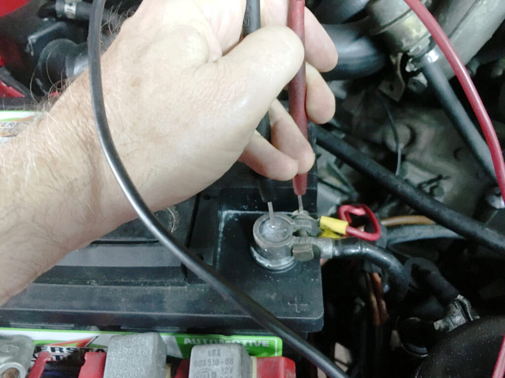
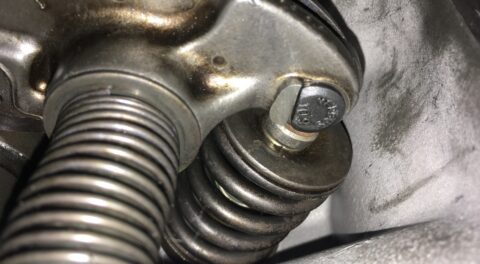
A voltage drop measurement conducted between the positive battery terminal and an attached ring connector.
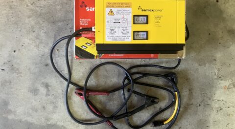
So there you go. If you have a circuit failure, you now have the mental tools to triage the failure into one of the five types and investigate them accordingly. For inexpensive items like small light bulbs, we often don’t even think about “circuit failure” or “troubleshooting.” The light isn’t working, ergo the bulb is probably blown. And it probably is. So you buy another one and pop it in. It usually solves the problem. With expensive load devices like fans and other electric motors, though, you want to be sure that the device really is the problem. This gets into the subject of electrical troubleshooting, which is a larger topic. My method is to, whenever possible, rule the component in or out by momentarily wiring it directly to the battery. If it doesn’t work, you have a failed component and need to put a new part on order. If it does work, then you need to begin looking at other causes of circuit failure, which usually leads to checking for voltage at the device and for a valid ground path.
Gotta go. Futurama is on. And it’s one of the episodes with “All My Circuits.”
—Rob Siegel
____________________________________
Rob’s newest book, The Best of The Hack Mechanic, is available here on Amazon, as are his seven other books. Signed copies can be ordered directly from Rob here.