
It’s been a slow automotive week BMW-wise, as my free time got eaten up by replacing the leaky gaskets under the marker lights on the roof of the truck, and replacing a seized caliper on my youngest son’s 2007 Corolla. So in lieu of real automotive work, I’m going to talk to you this week about automotive short circuits. I’ll explain how they’re a function of the “good” kind of resistance, but in the worst possible place.
First, I need to put on my Hack Mechanic professor’s hat and give you a short class on the basics of how electricity works in a car.
Electricity is defined as the flow of charge. You can get wrapped around the axle of what “flow” and “charge” actually mean, but for the sake of this discussion, we’ll use the convention that electrical current flows from the battery’s positive terminal to the “load device” performing the work (e.g., the light, the electric motor) and completes the round trip by returning to the negative battery terminal. On a little hand-held device with replaceable batteries such as a flashlight, connections are made directly to the positive and negative battery terminals. This is shown in the figure below.
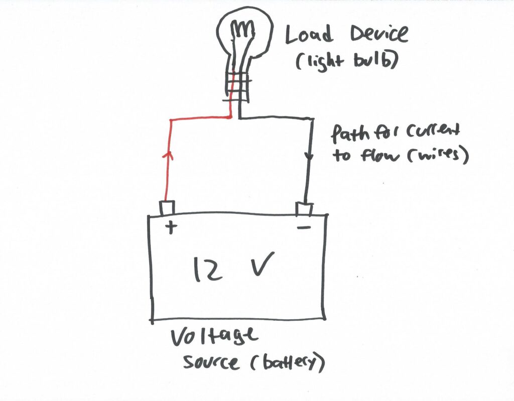
A load device like a light bulb connected directly to a battery.
If you haven’t worked on cars, you would assume that they’re wired this way as well, but early on in the development of the automobile, the utility of using the car’s metal chassis for one leg of the circuit became apparent, as that way, each device (each light or motor) could be connected using a single long wire to the battery and a short wire to the chassis. Initially, some manufacturers grounded the positive terminal and others the negative (and positive ground wasn’t only those wacky Brits; surprisingly, Ford was a positive-ground holdout until the mid-50s), but eventually the industry standardized on negative ground. Thus, the overwhelming majority of vehicles on the road have their negative battery cable connected to chassis ground. Individual wires carry electricity from the “+” battery terminal to every device, but nearly every device shares a common return ground path through the chassis. This is depicted for a simple circuit in the illustration below.
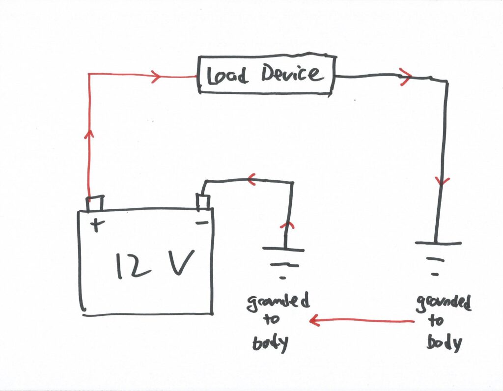
A simple circuit with a load device and chassis ground used as the return path.
Now, let’s add two more things to the circuit—a fuse and a switch. This way, current won’t flow through the circuit until the switch is engaged, and if the circuit draws more current than it should, the fuse will blow, stopping all current flow. Most (but definitely not all) circuits on a car look something like this.
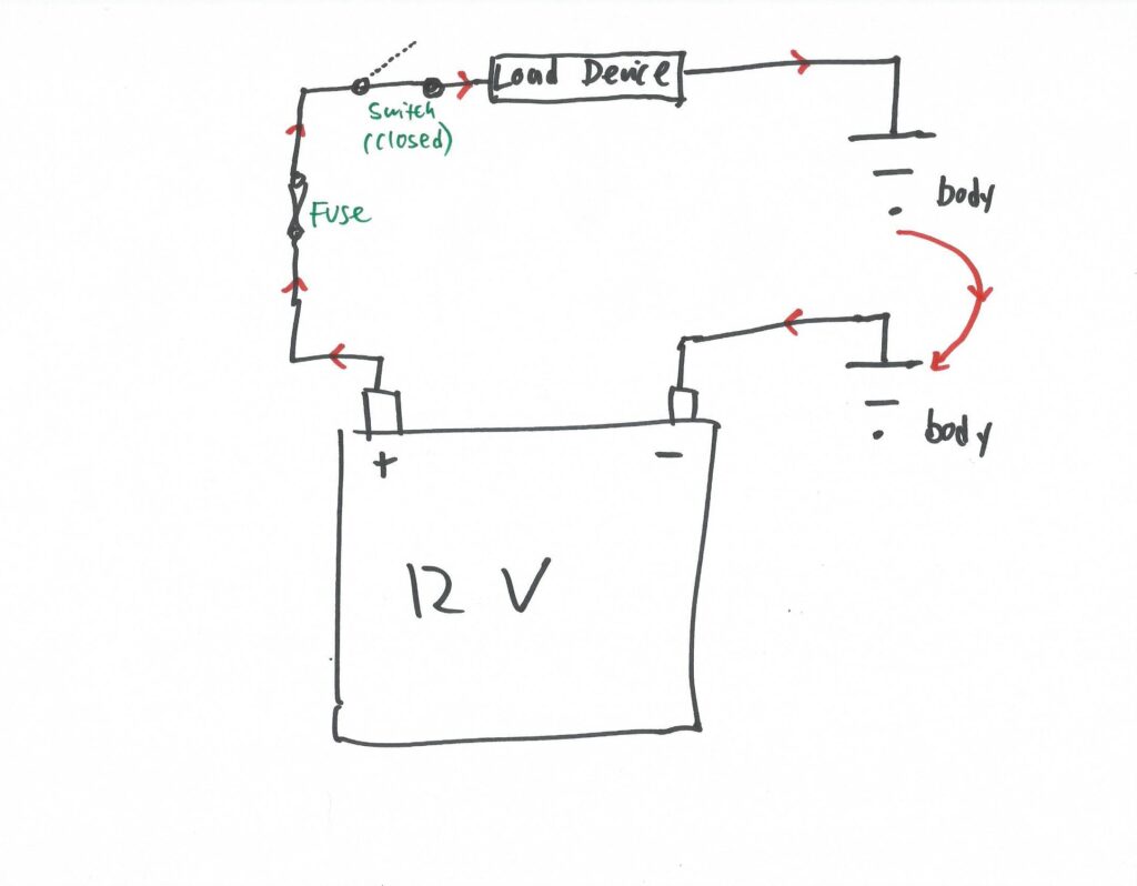
A simple but highly representative automotive circuit with a switch and a fuse.
In a car, when we say there’s a “short circuit” (or, to be, um, shorter, a “short”), what we almost always mean is that there’s a positive wire whose insulation has rubbed off, causing the bare copper strands inside it to accidentally touch ground, which causes the circuit to bypass the load device the wire is connected to. (There is such a thing as a “short to power,” but shorts to ground are far more common.) Two such shorts to ground are shown in the figure below.
Let’s say that the wire located between the fuse and the load device has rubbed through its insulation and touches the body of the car. This is short circuit #1 shown in green. In this case, current—a LOT of current—will suddenly flow from battery positive, through the fuse, through the wire, and directly to ground. Note that this will happen even though the switch in the diagram is shown open—that is, it’s called a “short circuit” precisely because it creates a circuit path that’s shorter than the intended one. Because the amount of current greatly exceeds the rating of the fuse (trust me, it does, and we’ll get to that), the fuse will blow almost instantly, stopping the current flow.
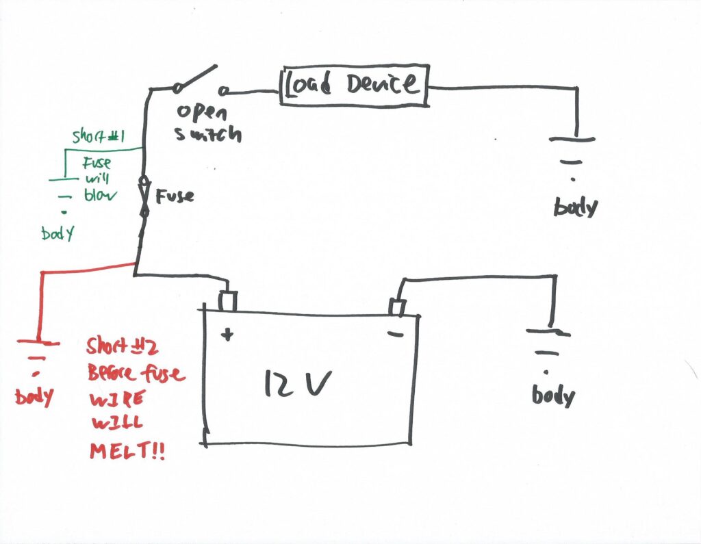
Short circuits to ground in two possible places.
If instead the rubbed-off insulation is in the section of wire before the fuse, then short circuit #2—the red path—will occur. As with short #1, a LOT of current will suddenly flow, but in this path, there is no fuse to blow, so there’s nothing to stop the current from flowing. This is the nightmare scenario—a dead short of an unfused circuit to ground, resulting in melted insulation, a burned wire, and possibly an electrical fire. Even if there’s not a conflagration, if the burned wire runs through a harness, the insulation on adjacent wires in the harness likely get melted as well. It’s a mess.
Wait—did you say unfused? How can circuits not have fuses? It’s surprising and a bit jarring how much wiring, particularly on a vintage car, isn’t protected by fuses. It’s understandable that the high-amperage wiring from battery positive to the starter, the alternator, and the fusebox itself are rarely fused (since these carry a lot of current, they’d need a really big fuse, and this is typically done in some locations on modern cars, but typically not on 50-year-old ones), but on a 2002, the ignition switch and the horn are unfused as well.
Twice above, I said “a LOT of current will flow.” How much are we talking about?
To answer that question, we need to do a little math. Bear with me. It’s just one equation. Okay, two. Well, two versions of the same equation, and then another, so sort of three. But that’s it. I promise. You can handle it. Your BMW itself has certainly caused you more pain than this.
First, let’s quickly revisit some of the terms we’ve already thrown around. There’s a waterfall analogy for electrical voltage, current, and resistance that many people find helpful.
Voltage is what’s supplied by the battery and alternator. A car is often referred to as having a 12-volt electrical system. Okay, the resting battery voltage is really 12.6 volts, and while the alternator is running, it’s actually putting out 13.5 to 14.2 volts, but let’s just call it 12 volts. In the waterfall analogy, voltage is the height of the waterfall.
Current (measured in amperes or “amps”) is the amount of water flowing over the waterfall.
Resistance (measured in ohms) is the diameter of the pipe the water is moving through.
So 170-foot-high Niagara Falls has a lot more water flowing over it than mile-high Yosemite falls, but if you try to pump either of their total output through a garden hose, you’ll have a problem. Either it’ll restrict the flow or the hose will burst.
If you don’t want to think in waterfall analogies, there’s an uncredited graphic that’s been shown in the electrical world for at least 50 years. It’s often referred to as “volts push amps through ohms.”
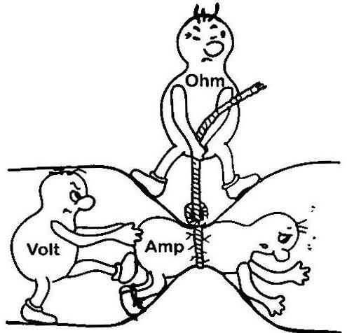
Poor little amp guy with volt’s boot in his butt.
The point with both analogies is that for a constant voltage, resistance (ohms) determines the amount of current that flows.
Personally, I say to hell with the analogies. The math says it all. Ohm’s Law gives the following relationship between voltage (V), current (I), and resistance (R):
V = I*R (voltage equals current multiplied by resistance)
For a simple circuit, voltage and resistance are constant, and what you’re really interested in is current. So solving this for current:
I = V/R (current equals voltage divided by resistance)
On a car with a 12-volt electrical system, you know the voltage, so if you know the resistance of a circuit, you can calculate the current. We can actually do that for a short circuit and explain why it causes the wire to melt.
You can look up the resistance of different wire gauges online. Ten feet of 12-gauge wire (roughly what would be used to wire a headlight or an electric fan) has a resistance of about 0.016 ohms. Plugging that into the formula above:
I = (12 volts) / (0.016 ohms)
= 750 amps
This says that if you have a dead short of 10 feet of 12-gauge wire, 750 amps will flow through it. I say “Yeesh!” but you might ask “Is that a lot?” You might be comfortable with units of volts because a car uses a 12 volt battery, but most people don’t have a good feeling for units of amps.
So let’s do it instead in terms of power in watts. People have a feel for watts, as that’s the unit for the power of light bulbs, heaters, generators, all sorts of things.
Which brings us to the second equation I need to torture you with—Watt’s Power Law:
P = I*V (power in watts equals current multiplied by voltage)
So, for our short circuit, the power in watts is calculated by:
P = (750 amps) * (12 volts)
= 9,000 watts
Nine. Thousand. Watts. In our little short circuit of one piece of wire. That’s the same as the maximum power output of one of these:
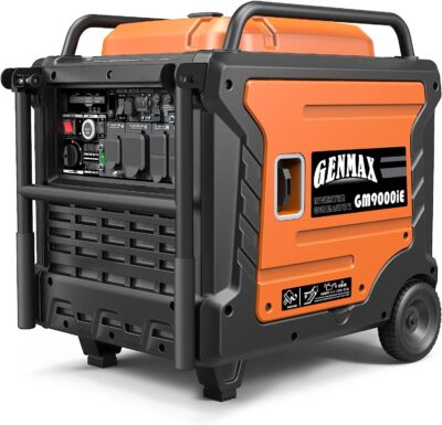
A 9,000-watt generator
Like trying to pump Niagara Falls through a garden hose, it’s just not going to work—a 12-gauge piece of wire may be able to carry 750 amps for a short amount of time, but without any kind of a load device (a light bulb, an electric motor) in the circuit, all that energy will go into heat. So the wire glows red hot, the insulation burns off, then the wire itself melts.
Actually, you hope it melts, because if it does, that breaks the circuit as long as the piece on the positive end doesn’t immediately lay itself back onto the body of the car. But if it doesn’t melt—if the exposed insulation-less wire just sits against the chassis—it’ll keep on passing enormous amounts of current generating enormous amounts of heat. Other things will catch fire. And before you know it, the car will go up in flames. If you’ve ever seen this happen, it’s astonishingly quick, often less than 30 seconds from smoke to full-on no-going-back totaled-car conflagration.
So, if wire has low resistance, and if low resistance causes a LOT of current to flow, why don’t defroster grids on rear windshields instantly melt? That’s a circuit made of nothing but wire, right? There’s no other “load device,” right? What’s the difference between that and a dead short circuit?
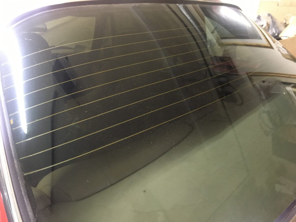
The mysterious defroster grid.
It’s actually a very good question that took me a while to understand. The answer hinges on two things—resistance, and the ability to dissipate heat.
A rear window defroster grid has substantially more resistance than standard piece wire, likely somewhere in the 1 to 5 ohm range, so by Ohm’s law, it should draw between about 2.4 and 12 amps. The wire in the defroster grid is designed to have that resistance, and is used for this application precisely because it both generates the needed amount of heat and has the ability to dissipate that heat without melting.
So, taking these two examples—the low-resistance wire that, when in a dead short, burns your car to the ground, and the high-resistance wire that properly de-fogs your rear windshield—what can you conclude about resistance? Is it good or bad?
It depends where the resistance is. I think about it this way:
Unintended high resistance is bad, but not dangerous. If your battery terminals are corroded, that extra resistance can prevent your car from starting. If there’s rust on the post where your wipers are grounded, that extra resistance can prevent the wipers from working. Whenever someone says “check your grounds,” this is what they’re talking about—checking for unintended high resistance that prevents a circuit from functioning.
But at the other end of the scale, unintended low resistance is REALLY bad and REALLY dangerous. That’s what a dead short to ground is—unintended low resistance. When you create a short circuit out of a low-resistance piece of wire on an unfused electrical circuit that can cause hundreds of amps to flow but has no way to dissipate the heat generated by it and there’s not a fuse to blow and stop it, it can catch the car on fire and burn it to the ground quicker than you can say “Gee, Ohm’s Law is way more interesting than I ever expected.”
I hope you enjoyed this little lesson from Professor Hack. Your assignment for next week is to check for chafed wires on your vintage cars.
—Rob Siegel
____________________________________
Rob’s newest book, The Best of The Hack Mechanic, is available here on Amazon, as are his seven other books. Signed copies can be ordered directly from Rob here.