Last week I described patching the muffler on my ’73 3.0CSi, “Rene”, and preparing to drive it to the inspection station to get stickered, only to find that the horn didn’t work.
Horn problems on vintage BMWs are fairly common. Often the cause is the horn itself. After all, it’s a vibrating metal diaphragm driven by a little electromagnet and it’s located up behind the grilles of the car, so after decades of weather, it’s not surprising that the diaphragm won’t move or the contacts are bad. But the problem can also be in the horn relay, or the button and its related contacts in the steering wheel. Of course, it’s always possible that it’s the wiring, but that’s the last thing I’d check, not the first.
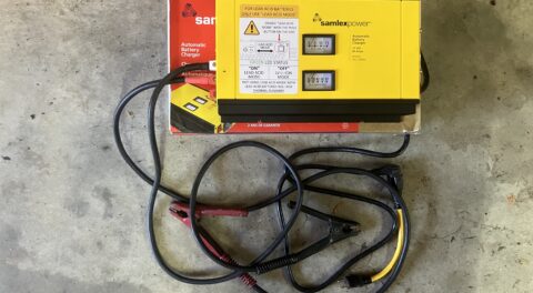
When any electrical component stops working, the first thing I want to know is if the component itself is at fault so I can get a replacement on order. So whether it’s a horn or an electric fan or a bulb, my first instinct is to wire the thing straight to the battery to remove any question whatsoever about whether or not the component works. However, because the horn is actuated by a relay, if you understand the basics of relay operation, you can often skip the wire-it-to-the-battery step.
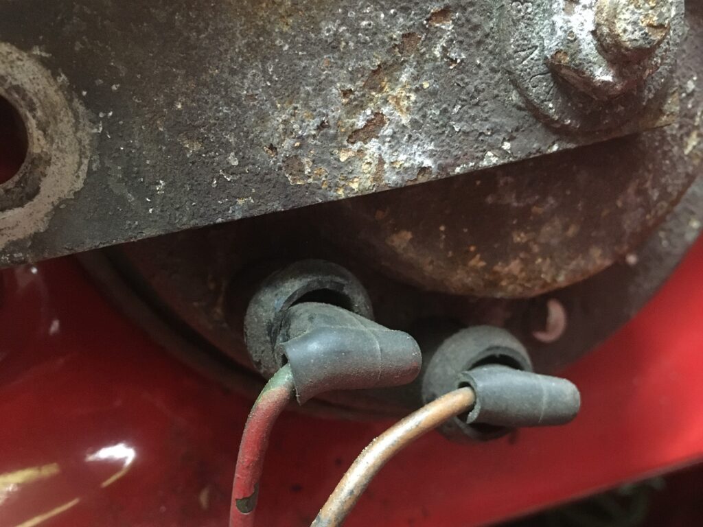
You can unplug these and substitute a pair of wires run to the battery, but it’s usually not necessary.
On a vintage car, the quick triage for the horn is to turn the key to the ignition position and hit the horn button. One of three things will happen:
- If the horn toots, obviously you have no problem.
- If the horn doesn’t toot, but you hear the horn relay click when the button is pushed, then the relay, the button and its related contacts, and the wiring between them are working, thereby isolating the problem to the horn and the wiring between it and the relay. In this case, wiring the horn directly to the battery will tell you which of the two it is.
- If you don’t hear the relay click, then the problem is either in the horn button and its contacts, or the wiring between them and the relay.
I’ve written a lot over the years about relays, but in a nutshell, a relay is nothing more than a remote-controlled switch where the internal contacts of the switch are pulled closed by an electromagnet, letting you close a high-current switch with a low-current switch. Nearly every relay used in a car for the last 40 years (and longer in German cars) has a set of standard “DIN” (it’s a German anagram) terminal numbers on it. 87 and 30 are the high-current terminals for the thing you want to turn on. 86 and 85 are the low-current terminals for the electromagnet. Feed 12V to 86 and ground to 85 (or vice versa; it doesn’t matter), and that energizes the electromagnet, which pulls the contacts together, connecting 30 to 87. If 30 is fed 12V and 87 is connected to the positive terminal of your device, and if the negative terminal of the device is grounded, it turns on. With most relays, the on-off switch that triggers it is employed on the 12V side of the electromagnet, but on a horn, because the horn button is on the steering column and you wouldn’t want it to accidentally short to ground, it’s switched on the negative side. A generic horn schematic is shown below.
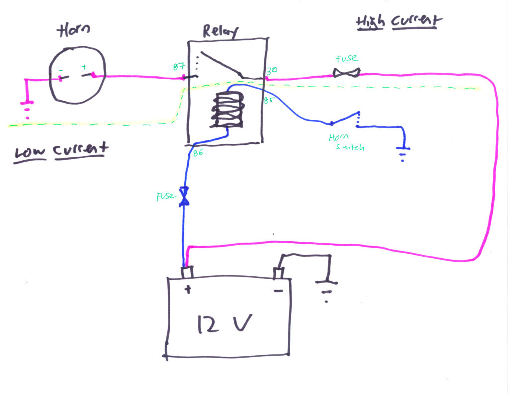
The basic electrical underpinnings of the horn.
The other thing you need to know is that, although I’ve simply labeled it above as “horn switch,” there are actually three separate pieces to it. There’s the horn button that you mash, which on modern cars is generally right in the center of the wheel, but on original 2002/E9 “bus” wheels is on the spokes. One side of the switch is usually connected directly to the metal body of the steering wheel, which, since it’s bolted to the metal steering column, is well-grounded. The other side of the switch goes to relay terminal 85 through a Rube Goldberg-like path. If the manufacturer ran a wire directly from the horn button to the relay, it would eventually break from being twisted when the wheel is turned, so instead, there’s an arrangement with a circular horn contact and a little sprung plunger. On a 2002, the circular contact is at the top of the steering column and the plunger is on the back of the steering wheel, but on an E9 they’re reversed. In either case, it’s very common for the 50-year-old Bakelite or plastic housing that holds the sprung plunger to split, allowing the spring and contact to spill onto the carpet. (Note that on a modern car with radio volume, channel, and cruise control buttons on the steering wheel, the multiple contacts are handled via a “clock spring,” but on an old car with just the horn, it’s just a single ring contact and a single plunger.)
So, with that backdrop, I cracked the key to ignition, put my hand on the horn relay, and reached my other hand inside to hit the horn button. I did not feel the relay click. Just to rule out the relay itself, I verified that the high beams worked, then swapped the horn relay with the high-beam relay. It made no difference. So my attention turned to the horn button and its contacts.
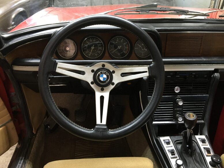
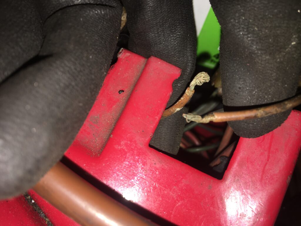
As I mentioned here, just before I drove Rene to the Vintage this past May, I replaced the steering wheel with a Momo wheel with brushed aluminum spokes that nicely complemented the piece of aluminum trim that runs beneath Rene’s wood dashboard. However, the Momo had previously been in a 2002 and thus had the sprung plunger on the hub instead of the contact ring that the E9 needed, so I had to do a little hacking to remove the plunger and put the round contact ring there instead. For these reasons, it wouldn’t have surprised me at all if this was the source of the problem. However, when I undid the cover that encloses the upper part of the steering column, I didn’t see anything amiss with the contact ring or the plunger.
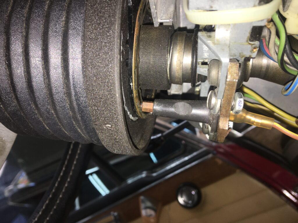
The horn contact ring is on the left, attached to the back of the steering wheel hub. The plunger housing is on the right, attached to the top of the column. The sprung contact is protruding from the housing and touching the circular ring contact. Looks good to me.
With nothing amiss to the eyeball, I had to roll up my sleeves and do actual electrical troubleshooting work.
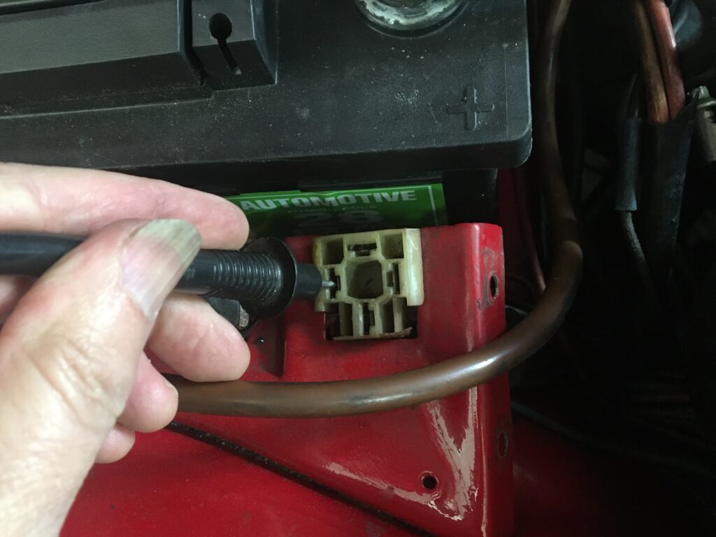
When troubleshooting a relay circuit whose problem isn’t obvious, you need to check the low-current and high-current circuits separately. The first thing to do is bypass the relay by inserting a jumper wire between terminals 87 and 30. This is commonly called “jumpering (or jumping) the relay.” The procedure is the same whether the relay is for a horn, the fuel pump, high beams, or any other common relay-triggered device. To bypass a relay, you first need to know which terminals are 87 and 30. You can almost always find this by turning the relay over to see the DIN numbers printed on the underside.
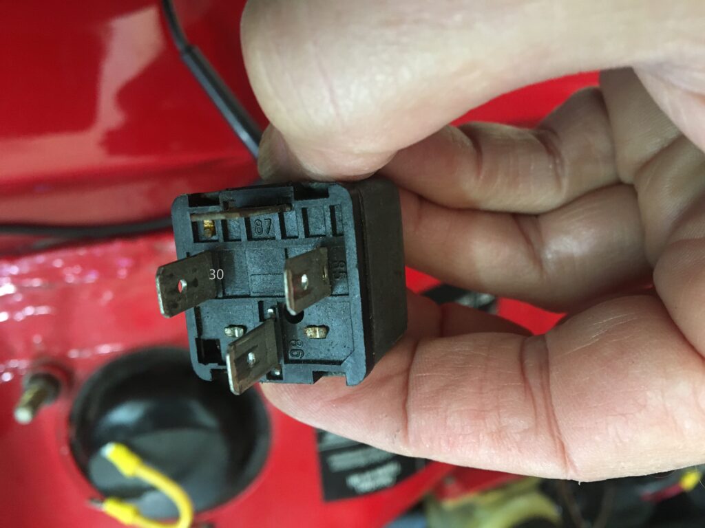
The DIN numbers on the underside of the relay.
Then, paying careful attention to the orientation with which the relay has to go back in its socket, transpose the numbers left to right to learn the DIN numbers of the female terminals in the socket. Write them down on a piece of paper if you need to. Then insert a jumper wire from 30 to 87. If it’s just for a quick test, any wire bigger than speaker wire will do, but if you intend to leave the relay bypassed, it’s best to use heavy-gauge wire and crimp connectors onto the ends.
A jumper inserted between relay socket pins 30 to 87.
If your device (in this case, the horn) springs to life, then there’s nothing wrong with the high-current portion of the wiring. In my case, Rene’s horn blared immediately. If it hadn’t, I would’ve needed to check that terminal 30 has 12V on it, that with the jumper in place 12V is present at the horn, that the horn actually works, and that it’s properly grounded.
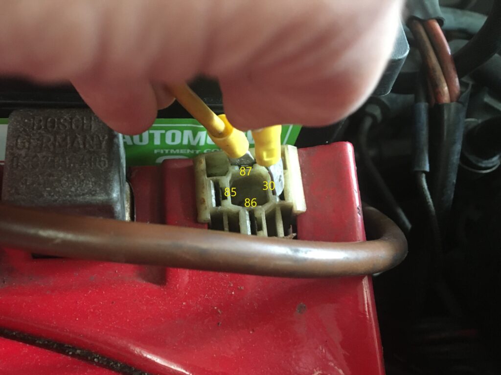
That left the low-current side of the relay. If you google “12V relay wiring,” you’ll usually see that 86 is the positive side of the electromagnet and 85 goes to ground, but they can be reversed, so it’s best to check them both at the relay socket with a multimeter. On mine, 86 was indeed the 12V side, and 12V, or at least the ignition-on-but-engine-not-running low version of it, was present.
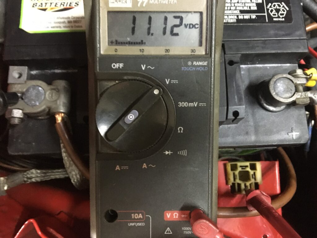
A little low, but close enough for horn troubleshooting.
That left the negative leg of the low-current side. For the electromagnet in the relay to be pulled closed, hitting the horn button would need to complete the path from terminal 85 to ground, so I set my meter to measure resistance, put one probe in 85 and the other on the negative terminal of the battery, and hit the horn button. If the horn button completed the ground path, the meter should’ve read essentially zero resistance, but instead it read “OL,” which in Fluke meter-speak means “over limit,” or infinite resistance. Conclusion: The problem was that hitting the horn button wasn’t grounding terminal 85.
Insert Borg “resistance is futile” joke here.
Now, there are two kinds of mechanics in this world—those who reach this point and say “I need a wiring diagram,” and those who don’t, or won’t, or at least resist it until they really do. I personally can’t stand reading wiring diagrams, and generally find their importance overrated. There are a few reasons for this. One is that if you understand how relays work, and know that you can pull them out of their sockets, read the DIN numbers on the bottom, then transpose the numbers so they apply to the sockets, you don’t need to look at a wiring diagram to see which wires are for which legs on the relay. Another reason is because most electrical problems aren’t caused by broken wires in the middle of wiring paths. That’s actually pretty rare. Instead, problems are almost always in components, or at the ends of wiring paths—in terminals that have pushed their way out of 50-year-old Bakelite sockets, or in wires that have broken off the ends of terminals.
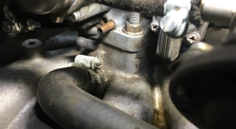
Unfortunately, I didn’t see anything wrong with the top of the relay socket, so I needed to look under it. To do that, I needed to slide it out. And to do that, I had to remove the battery hold-down clamp and shove the battery over. Once I did, I turned the socket over, and saw electrical tape on the brown wire leading to one of the terminals.
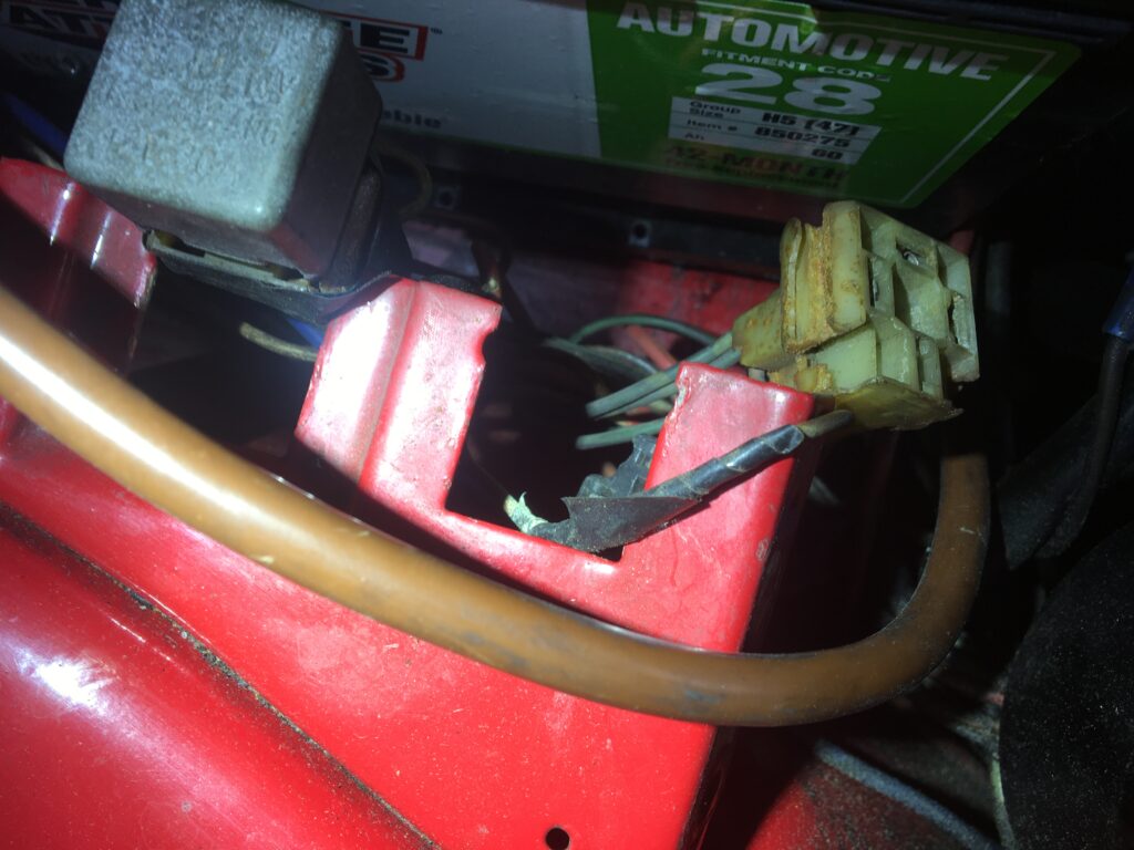
As they say on Law and Order, ka-KUNG!
I’ve owned this car for 37 years, and I’ve done many unsavory electrical things in service of, oh, let’s see… the retrofitted air conditioning, the retrofitted L-Jetronic fuel injection, and the retrofitted heater control valve to make it so the heater box isn’t radiator-hot in the middle of summer… but I had absolutely zero recollection of cutting and splicing a wire under the horn relay with electrical tape.
As I began to unwrap the tape to see what sins it was hiding, one of the wires simply pulled out of it. When it all was exposed, it was clear that the wires had simply been twisted together with no solder or crimped connector to hold them.
Well, THAT explains a lot.
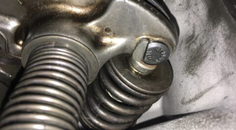
I reconnected it using a proper butt-splice connector that, when heated with a heat gun, melts a glob of solder onto the wires as well as heat-shrinks the tubing to make it weathertight.
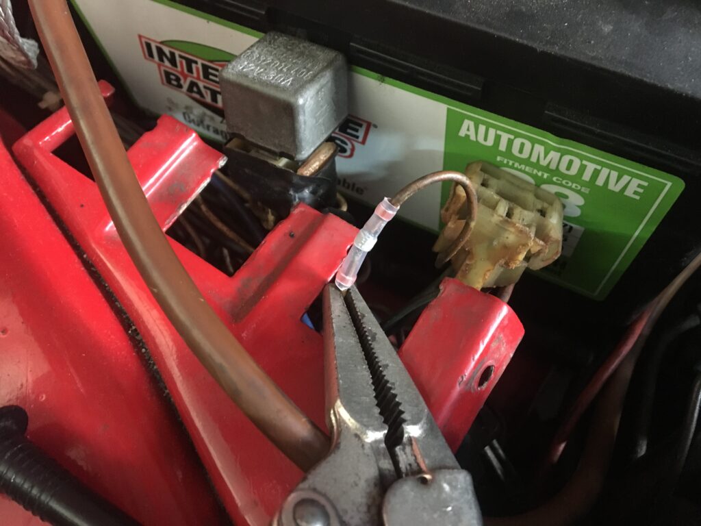
The in-process weathertight butt splice.
And, with that, the horn sprang back to life, and I got the car inspected.
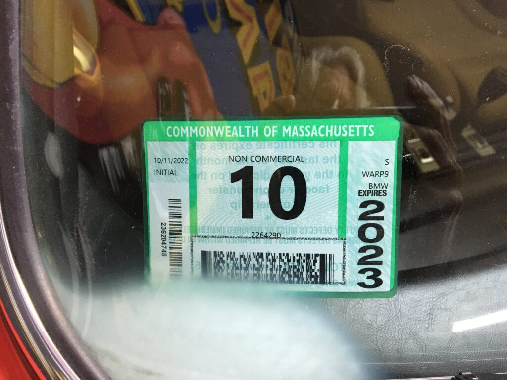
The fog in the lower corner? It’s a long story.
Just in time, too, as I’m rapidly running out of foliage to drive in. Hey, if nothing else, Rene is ready for the next inspection.—Rob Siegel

I’M NOT READY TO PUT YOU AWAY FOR THE WINTER!!
____________________________________
Rob’s new book, The Best of The Hack Mechanic, is available here on Amazon, as are his seven other books. Signed copies can be ordered directly from Rob here.